FreeCAD is a parametric 3D modeling software and it is also free and open-sourced. The latest versions of FreeCAD are equipped with a FEM module, which is implemented as an integration of Calculix solver. In this post we will try out the FEM module by creating and calculating a simple laterally loaded cantilever solid beam and then comparing the result to an equivalent case in Ansys verification manual. Note: If you are promptly looking for a complete open-source FEA tool for some actual analysis work, you may want to read the conclusion section at the end of this article first.
Let’s start by installing FreeCAD. I recommend you install the latest stable version of FreeCAD because the FEM module requires version 0.16.6377 or above. In this tutorial I use version 0.16.6712 on Ubuntu 16.04. The installation is trivial. Assuming you are on Linux system, you can install FreeCAD by typing in Terminal:
sudo add-apt-repository ppa:freecad-maintainers/freecad-stable

sudo apt-get update

sudo apt-get install freecad freecad-doc && apt-get upgrade
After installation and before diving into the software, let’s have a closer look at the calculation example. This description below is directly from Ansys VM5:
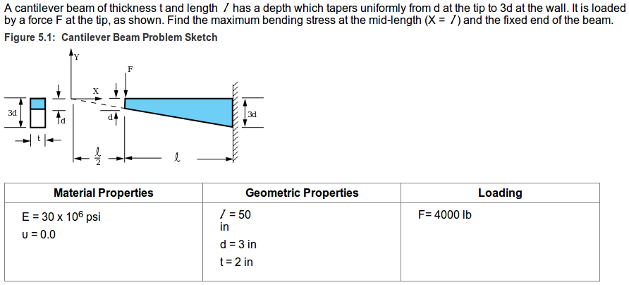
As you noticed the input values above are not in SI units. There are different units and a some kind of unit conversion tool available in FreeCAD. However, and regardless of our personal unit preferences, we will convert the problem in FreeCAD to mm/kg/s/degree -system, which is also the initial unit system in FreeCAD. It is named as Standard option in User system under Units settings menu. Check your unit setting at Edit > Preferences > Units. Here are the input data values in SI-units: E = 206842,72 MPa, v = 0.0, l = 1270 mm, d = 76,2 mm, t = 50,8 mm, F = 1814,37 kg * 9,81 m/s² = 17799 N.
Next I will guide you through a simple modeling of tapered cantilever beam. After that we will pre-process, solve and post-process the solution in the FreeCAD FEM module. This blog article does not contain any extra guidance for FreeCAD usage. You may find some further readings at FreeCAD wiki sites.
Let’s start working by creating a new empty document (Ctrl + N) and clicking open the Workbench menu where the initial status is Start.

Switch it to Complete. This selection makes visible a wide selection of tools in the tool bar.

Select create a new sketch (shown in picture above). Keep XY-Plane as sketch orientation and click OK. Select a polyline tool from the toolbar. Then draw a tapered shape as the one below. Do not be concerned about the dimensions yet. But you can let the software automatically set the vertical and horizontal constrains at the three orthogonal edges.
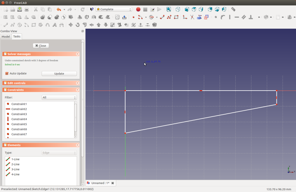
Then activate the horizontal line by clicking it (becomes green colored). Select fix the horizontal distance between two points or line ends (Shift + H) from the tool bar. Set the distance to 1270 mm. Then select the vertical line on left hand side and assign respectively fix the vertical distance between two points or line ends (Shift + V) with distance 228,6 mm. Then similarly on the right side set dimension to 76,2 mm. Now the sketch should look like this:

If any constrain conflicts arise during the dimensioning, delete all inappropriate constrains in a Constrains window of a Task tab on the left. Now your sketch should be fully constrained. Click Close on the Task tab. Next, find a button Pad a select sketch on tool bar and click on it (Tip: it is pointed in the picture below). In Pad parameters add length to 50,8 mm and click OK. Now is a good moment to save the model, and cantilever.fcstd may be a good file name for the project. At this point the model is a solid part and should look like this:
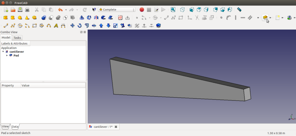
As the geometry is ready, we will switch on the FEM Workbench. Select FEM from the Workbench menu (change it from Complete). The tool bar is changed. Select create a mechanical analysis (N, A) from the tool bar (the button has yellow letter “A”). A new entity labeled as MechanicalAnalysis appears to a Labels & Attributes window on the left. If you expand that title, you can see the analysis contains a solver CalculiX.
Next let’s define the material used in the analysis. Click the creates or edits the mechanical material definition (M, M) button (button icon: yellow ball-a-like). In Mechanical Material menu, change Material from None to Steel-Generic. Then change the Properties as follows, Young’s Modulus to 206842,72 MPa and Poisson Ratio to 0,001. Unfortunately, in FreeCAD we cannot set Poisson’s ratio to zero, so we choose the minimum allowed value. This will cause small but negligible error in our calculation since a small shear strain will be included in the deformation results. The Material properties should look like this (Density is not important now):

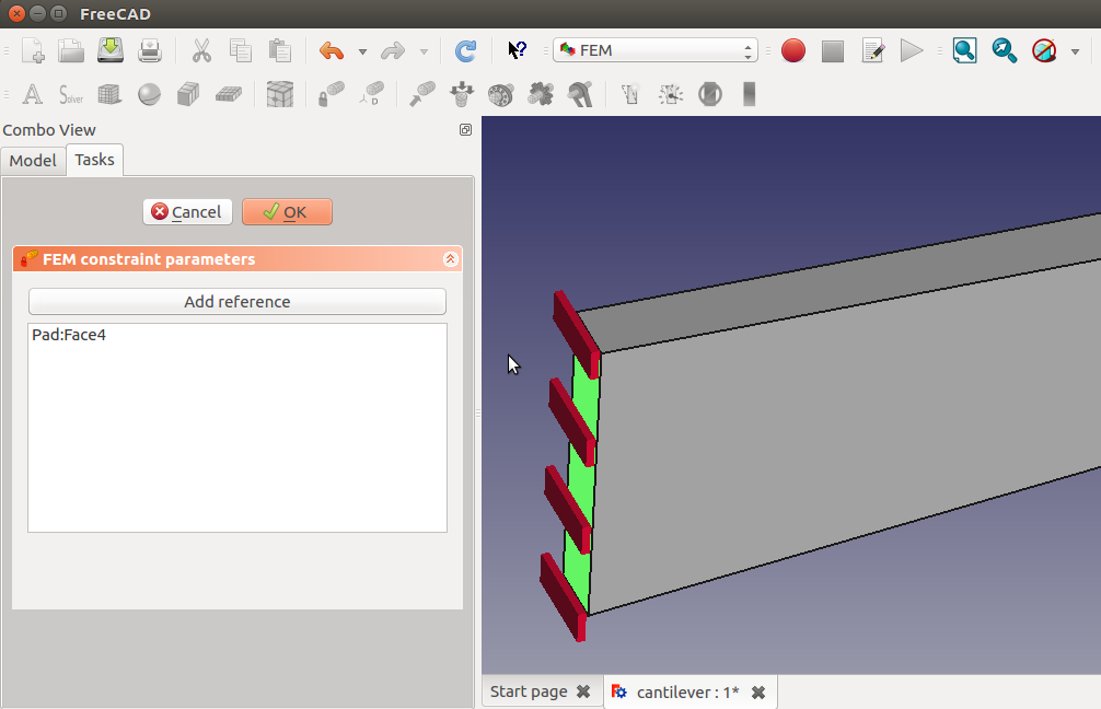
Click OK. Then select create FEM constrain for a fixed geometric entity from the tool bar (button icon looks like a red lock and yellow part). Then select the end face of the higher end of the beam and click OK.
Next, select create FEM constrain for a force acting on a geometric entity (button icon: red arrow and yellow part). Now, first: select the horizontal top edge of the lower end of the beam, second: click Direction button in FEM constraint parameters menu, and third: select one of the vertical edges for a reference for the force direction. Make sure the force arrows point downwards, and if not, opt-in the Reverse direction selection. Set the Line load to 17799 (total force in Newtons).
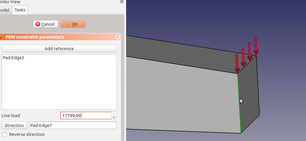
Remember to save the project. Next, let’s mesh the model. First activate the Pad part and then click create FEM mesh from shape button (pointed in the picture below).
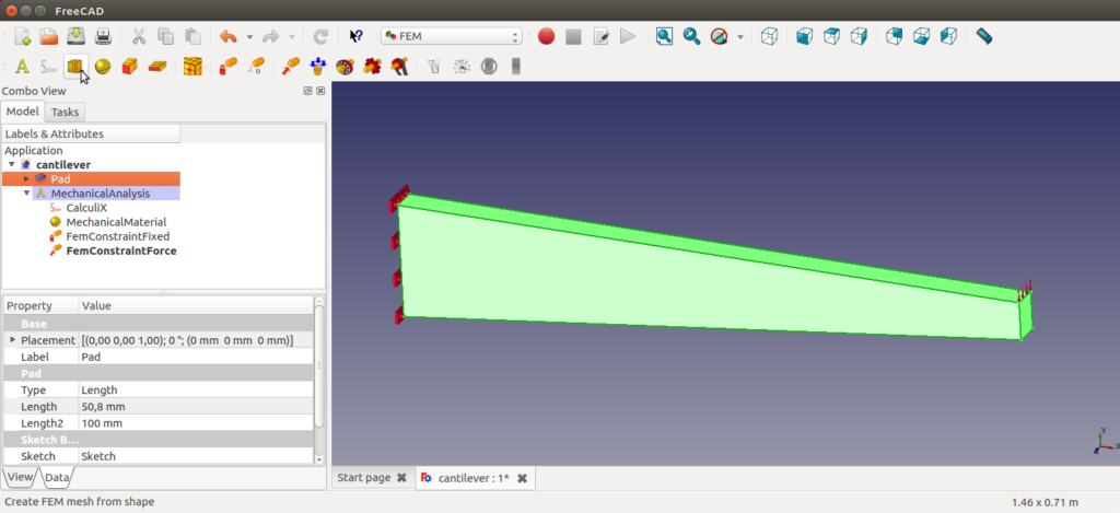
Let’s keep the default meshing settings and click OK. Now, we need to drag and drop the created Pad_Mesh mesh under the MechanicalAnalysis. I have no idea why FreeCAD creates meshes outside the analysis scope by default. However, it must be fixed, so grab the mesh entity and drop it inside the MechanicalAnalysis in the Labels & Attributes list.
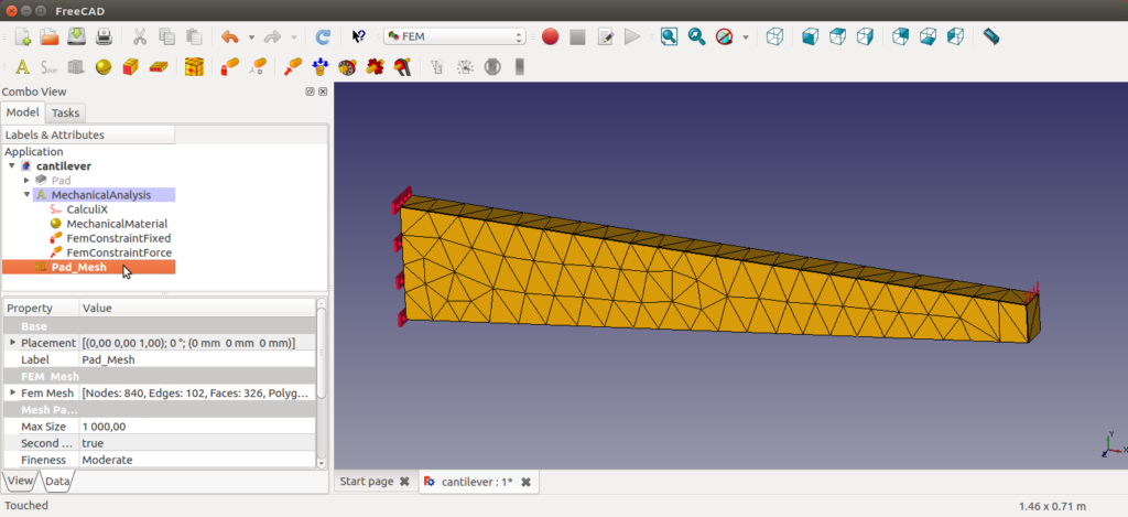
Then activate the Calculix solver so that the dialog to start the calculation of the selected solver (S, C) (button icon: deformed yellow rectangle) becomes enabled in the tool bar. Click on it.
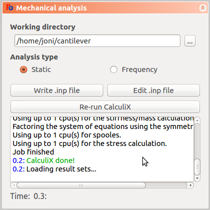
In Mechanical analysis menu (shown above), set an easily findable directory for the text files written for the analysis (not necessary if you are not interested in checking the files later). Then click on Write .inp file. After that hit Run CalculiX. The analysis is done, click Close.
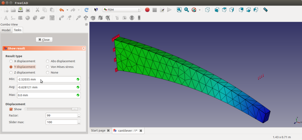
Now there are results available. You can access the results by selecting show the result information of an analysis (S, R) button from the tool bar (button icon: color scale). In show results menu you can now choose which results to look at. In this case, the only appropriate plots available are Y displacement and Von Mises stress.
Deformation in vertical direction looks like this:
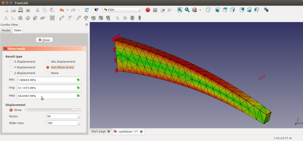
Von Mises stress (a very commonly used yield criterion for steel structures) for the beam structure looks like this:
Now we can try to check if the result is aligned with the target values given in Ansys VM5.
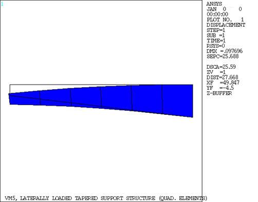
The maximum deflection calculated by Ansys (no analytical target value provided for displacement) for this laterally loaded tapered beam is shown in the picture below (directly from VM5). You can see in the Ansys plot below that the maximum displacement (DMX) is 0.097696 inches, which is 2,48 millimeters. In our FreeCAD Y displacement plot we had max displacement 2,52 mm (containing a very small shear strain).
The stresses are difficult to compare because there are bending stress target values given in the Ansys VM5, whereas FreeCAD provides the von Mises stress only. In our case von Mises stress probably contains a notable portion of shear stress and hence cannot be compared to any bending stress component. However, we can put the values side by side just to check that there is no huge scale error. The target value (in VM5) for bending stress at the mid section of the beam is 8333 pounds per square inch, which is 57,45 MPa. FreeCAD post-processing does not provide any probing tool to enable locating the local values of the results. So without having any idea where it is located we can only look at the global maximum, which is 58,05 MPa.
Conclusion
The results for displacement seem to be reasonable. And in general, FreeCAD FEM module feels relatively easy to use. But the pre-processing tools seems to provide the very basic constrain settings only. Post-processing is also very limited. Especially, verifying the results is difficult or impossible because one cannot see the total support reaction, which is normally the first thing to check after running any mechanical FEM analysis. Also different stress components are not presented individually. For serious analysis work some kind of probe tool would also be necessary.
However, the FreeCAD FEM module is very good as a first try to integrate FEA capabilities into FreeCAD modeling software. Hopefully the development will continue. The Calculix solver is a powerful tool and obviously a good choice. Still, the GUI features of the FEA module are currently so limited that FreeCAD alone cannot yet be recommended for any serious FEM analysis work. Actually, there is currently very big risk that experienced users will not use it for real analysis work while some curious and inexperienced users may blindly trust the limited results provided, and draw design decisions based on them (which actually may be the main problem of every CAD integrated FEM tool). So FreeCAD developers, keep up the good work! The bigger the user base and the community, the bigger the power and trust in the software.
What are your thoughts about the FEM implementation in FreeCAD? Please drop me a line in the comment section below. And thanks for reading!
Excellent example and detailed comparison with a very well-known commercial software (ANSYS). Well done, keep up the good work ! (Cheers from Athens, Greece)
Thank you very much, I’m glad you liked it!
Thanks, Excellent example!
I need this example in freecad 18.3
Can you help me please?
Hi Tommy,
I quickly run through the task with 0.18 version. For starters, try choosing the Part Design -> Create body -> Create sketch -> select plane -> OK. After ready with sketching, choose Sketch Tools / Pad and define the thickness. I quess the rest follows pretty much the original guidance, with some diffrence in details. Hope this helps for now!
Unfortunately I don’t have time to make a new version for the blog post now, but I’ll do it in the future for some bigger version change if FreeCad.
BR, jolahde
Really like this example and FreeCad concept , in general. My initial impression is that there is no way to actually check that the model is correct. What exactly are the reactions at the constrained end?
The may be correct, but, how do I freebody this part? Maybe I am too new at this, but, I keep hunting for an example of a cantilever beam where the reactions and deformation are checked against an exact solution.
40 years of finite element modeling (for me) always comes back to having the ability to check the basics for user errors.
Your conclusion pretty much sums it up I think.